
 Before you can begin the hull side assembly, the hull bottom and deck assemblies must be completed.

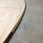
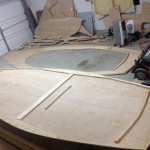
 Then we start with the transom.
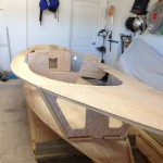
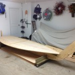
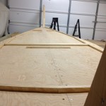
 Next is to place the completed deck assembly on top of the bulk heads and the tip of the stern. These will be attached later.
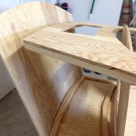
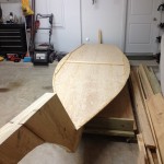
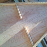
 Now the Lazarette is attached to the bottom stringer. Notice how there is no curvature in either component. This is the fun part and will require a lot of muscle power to attach.
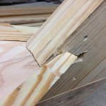
 I ended up with a 2″ shortage some how when I pulled the Transom and deck together. When I tried to attach the two it pulled away from the stern block.
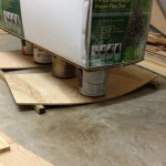
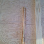
 To help make this easier, I put my 9′ christmas tree which seems to weigh a ton on top of paint cans centered on the Lazarrette and Transom pieces for several days.
 After shifting everything around, something changed and this actually worked pretty well and everything lined up. I would still recommend some extra help so your hands are free to glue and screw all the components together properly.
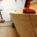
Now notice here that there is a little extra curvature across the top of the deck. After all the stress of the previous gapping, I messed up here and should have laid the deck across the top of these parts to create a curved deck. Opps!
 So the deck turned out to be flat between the Transom and the Lazzarette, but I actually don’t mind it this way. The hatch will be easier to build.
*** Now at this point I took things out of order from the plan and build the cabin walls, rafters and roof, hatch openings and surrounding stringers, mast box, bow gussets, bowsprit bits and anything else that would be easier to do without having to climb in and out of the boat, before I put the hull sides on. ***


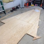
Fore Starboard panel.

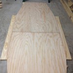
Aft Starboard panel.


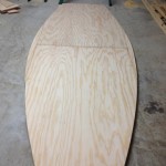
Both sides complete.


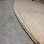
Before / After